Address
304 North Cardinal
St. Dorchester Center, MA 02124
Work Hours
Monday to Friday: 7AM - 7PM
Weekend: 10AM - 5PM
Address
304 North Cardinal
St. Dorchester Center, MA 02124
Work Hours
Monday to Friday: 7AM - 7PM
Weekend: 10AM - 5PM
Track light spacing worked out from beam angle and mounting height: pool width, pitch, overlap and head count, with a full height-by-beam table and FAQ.
Track lighting layout is usually taught as one number: the distance between heads. That is only half of it. The other half is the height those heads are hanging at, because the height sets how wide each head’s pool of light lands on the floor — and the pool width is what the spacing has to be measured against.
So this article works the layout as a two-variable problem. You pick a beam angle, you know your mounting height, and the pool, the pitch and the head count all follow from the same three lines of arithmetic. Everything below is worked in feet and metres, with every number computed rather than quoted, so you can substitute your own room and get your own answer.
For a 24° head in a ceiling 9 ft (2.74 m) above the floor, each head paints a pool 3.83 ft (1.17 m) across. At the 30 % edge overlap that suits general lighting, that is a centre-to-centre pitch of 2.68 ft (0.82 m), which puts 7 heads on a 20 ft rail with 1.97 ft of margin at each end.
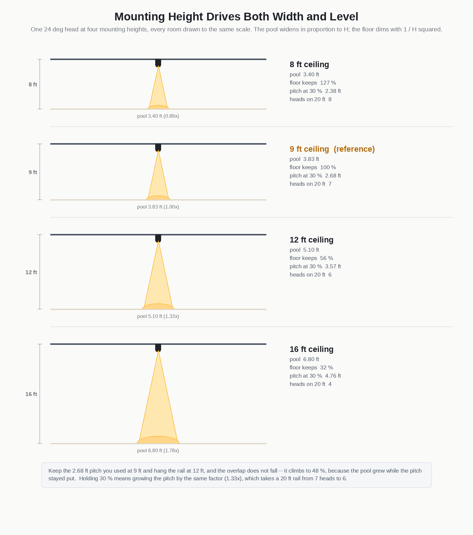
Change the height and every one of those numbers changes with it. Hang the same head at 12 ft and its pool becomes 5.10 ft, the pitch you need rises to 3.57 ft, and the same 20 ft rail takes 6 heads instead of 7. The floor also gets dimmer — about 56 % of the 9 ft illuminance, because light falls off with the square of the distance.
That is the whole method. The rest of this article is the arithmetic, the table, and the cases where the simple version breaks.
Everything else is built from these. Both are geometry, not rules of thumb, so they hold whether you are working in feet or metres as long as you stay consistent.
Pool width from beam angle and height: D = 2 × H × tan(θ / 2)
Pitch from pool width and overlap: s = D × (1 − overlap)
Where H is the vertical distance from the lens to the surface being lit (normally the floor), θ is the beam angle printed on the fixture, and overlap is the fraction of each pool that you want shared with its neighbour: around 20 % for accent work, 30 % for general lighting, 40 % where you need genuinely even task light.
Note the tan(θ/2). A beam angle is quoted as a full cone, so you always halve it before taking the tangent — that is the single most common arithmetic slip, and it doubles the error if you forget it. The same relation runs backwards, which is useful when you have an existing layout and want to know what beam angle it implies: θ = 2 × atan(D / 2H).
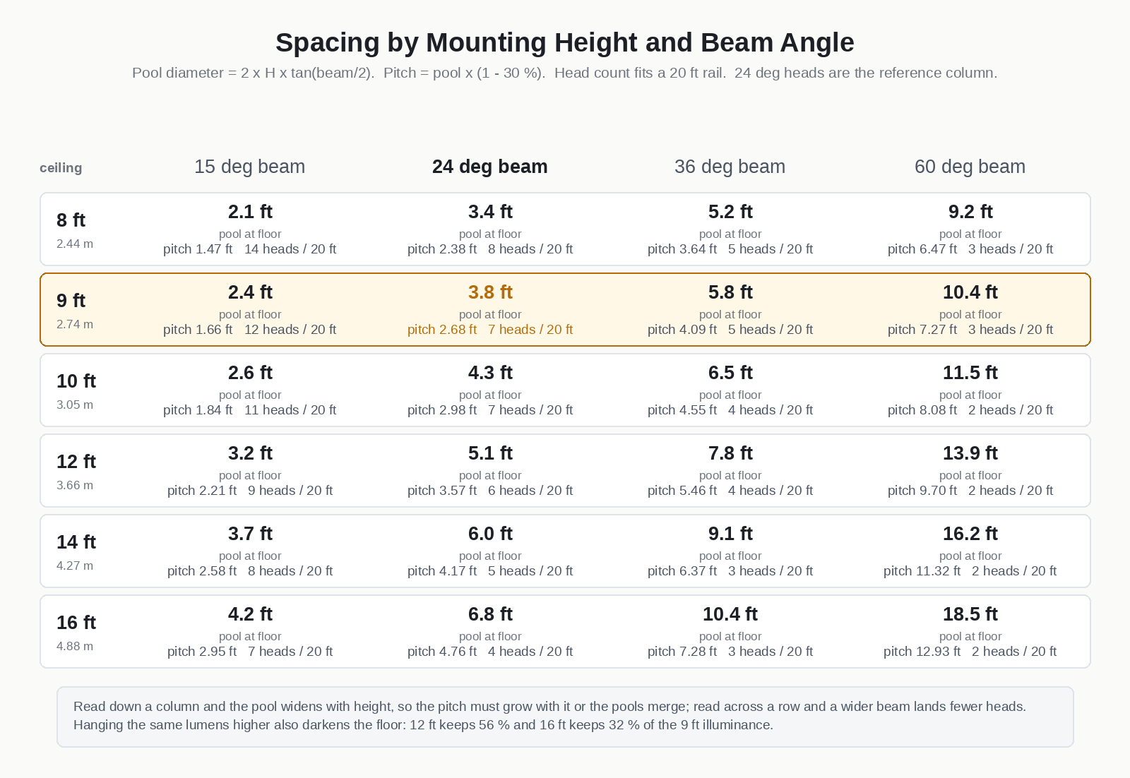
D = 2H·tan(θ/2) and s = D×(1−0.30). The highlighted row and column are the 9 ft / 24° case worked in the text.This is the table to keep. Read down a column to see what height does to a fixed beam angle; read across a row to see what a wider beam does at a fixed height. Pitch column assumes 30 % overlap and 20 ft of rail.
| Ceiling height | 15° pool / pitch | 24° pool / pitch | 36° pool / pitch | 60° pool / pitch |
|---|---|---|---|---|
| 8 ft (2.44 m) | 2.1 ft / 1.47 ft | 3.4 ft / 2.38 ft | 5.2 ft / 3.64 ft | 9.2 ft / 6.47 ft |
| 9 ft (2.74 m) | 2.4 ft / 1.66 ft | 3.83 ft / 2.68 ft | 5.8 ft / 4.09 ft | 10.4 ft / 7.27 ft |
| 10 ft (3.05 m) | 2.6 ft / 1.84 ft | 4.3 ft / 2.98 ft | 6.5 ft / 4.55 ft | 11.5 ft / 8.08 ft |
| 12 ft (3.66 m) | 3.2 ft / 2.21 ft | 5.10 ft / 3.57 ft | 7.8 ft / 5.46 ft | 13.9 ft / 9.70 ft |
| 14 ft (4.27 m) | 3.7 ft / 2.58 ft | 6.0 ft / 4.17 ft | 9.1 ft / 6.37 ft | 16.2 ft / 11.32 ft |
| 16 ft (4.88 m) | 4.2 ft / 2.95 ft | 6.80 ft / 4.76 ft | 10.4 ft / 7.28 ft | 18.5 ft / 12.93 ft |
Two things worth noticing. First, the 60° column produces pools wider than most rooms are worth lighting — an 18.5 ft pool in a 16 ft ceiling is not a pool, it is the whole floor, which is why wide beams work best as fill rather than as the layout. Second, the 15° column barely changes width between 8 ft and 16 ft in absolute terms, but the pitch doubles; narrow beams are the ones where height matters most for the head count.
Both relations come straight from the geometry of a cone rather than from a rule of thumb. The formal definitions of the lighting quantities involved are published by the Illuminating Engineering Society, and the US Department of Energy has a plain-language overview of how LED light output is specified and compared.
Widening the pitch on a tall ceiling is only half the adjustment. The other half is that the floor gets darker, and it gets darker faster than most people expect.
Illuminance falls with the square of the distance from the source. Same fixture, same lumens, hung higher: at 12 ft the floor keeps 56 % of what it had at 9 ft, and at 16 ft it keeps just 32 %. To hold the 9 ft floor level at 12 ft you need roughly 1.78× the lumens at the source, and at 16 ft about 3.16×.
This is where tall rooms go wrong. The layout gets scaled up properly — six heads become four, the pitch grows — but the fixtures stay the same wattage, so the room ends up evenly lit and simply too dim. If you are lighting a 14 ft ceiling, budget the lumens for the height first and choose the beam angle second.
Here is a trap that catches almost everybody working from a 9 ft plan onto a 12 ft ceiling. Suppose you keep the 2.68 ft pitch and just hang the rail higher. You might expect the pools to drift apart.
They do the opposite. The pool at 12 ft is 5.10 ft wide, so a 2.68 ft pitch now overlaps them by 48 % — the overlap rose from 30 %, because the pool grew 1.33× while the pitch stayed put. You end up with a tighter, hotter run than you drew. Holding 30 % means growing the pitch by that same 1.33×, to 3.57 ft, which takes a 20 ft rail from 7 heads down to 6.
The rule in one line: if the pool grows by a factor, the pitch has to grow by the same factor. Anything else silently changes the overlap you thought you were specifying.
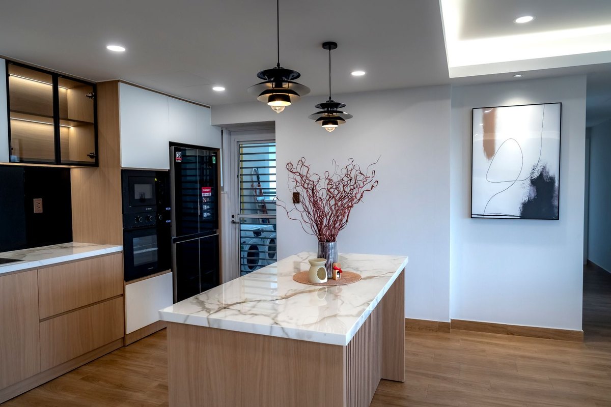
The overlap is the design decision; the pitch is just arithmetic. Three bands cover almost every room.
| Effect | Overlap | Pitch at 9 ft / 24° | Heads on 20 ft | Use it for |
|---|---|---|---|---|
| Accent | 20 % | 3.06 ft | 7 | Separate pools, visible pools, artwork, features you want read individually |
| General | 30 % | 2.68 ft | 7 | Living space, dining, bedrooms — pools still readable, no hard dark gaps |
| Task | 40 % | 2.30 ft | 9 | Kitchen worktops, desks, anywhere shadow between pools becomes a problem |
Then the head count. Spread the heads so the end margins match, which means the first and last head sit half a pitch in from each end of the run:
n = floor((L − s/2) / s) + 1
For a 20 ft rail at a 2.68 ft pitch that gives 7 heads, with the first at 1.97 ft and the last at 18.03 ft. The pitch between neighbours is exactly s all the way along, and the margins absorb the remainder — which is nearly always better than stretching the pitch to fill the run, because a stretched pitch quietly changes your overlap.
The table is the fastest route, but it is worth seeing how the same method moves for real rooms. The pattern to watch is that the head count is driven by the pitch, and the pitch is driven by both the beam angle and the height at once.
Pool 3.83 ft, pitch 2.68 ft, 7 heads on 20 ft. This is the reference case, and it is where most residential track layouts should start.
Pool 2.4 ft, pitch 1.66 ft. The same rail now needs 12 heads to do the job the 24° heads did with 7. Narrow beams buy you punch and pool definition; they do not buy you coverage. If the goal is general light, going narrower mostly means buying more fixtures.
Pool 5.10 ft, pitch 3.57 ft, 6 heads on 20 ft — and 1.78× the lumens to hold the floor level.
Pool 3.40 ft, pitch 2.38 ft, 8 heads on 20 ft. Low ceilings are where a standard 24° head starts to feel cramped; either accept tighter spacing or drop to 15° to keep the pools from merging into one flat wash.
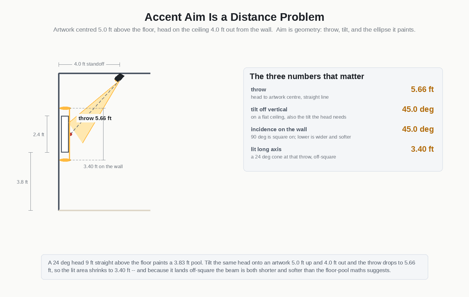
Everything above assumes the head points straight down at the floor. The moment you aim a head at a wall — artwork, a shelf, a stone face — the height that matters is no longer the ceiling height, it is the throw: the straight-line distance from the lens to the thing you are lighting.
Take a head on a 9 ft ceiling, 4 ft out from the wall, aimed at the centre of a piece hung at 5 ft. The throw is not 9 ft, it is √(4² + 4²) = 5.66 ft. A 24° head at that throw paints about 3.40 ft of wall, not the 3.83 ft it would paint on the floor — and it lands off-square, so the lit shape is an ellipse rather than a circle.
The tilt needed is also geometry: because the head sits 4 ft out and 4 ft above, the axis sits 45° off vertical. On a flat ceiling that is exactly the tilt the fixture has to carry, so a head with only 30° of adjustment physically cannot reach this artwork from this position. Move the rail closer to the wall and both numbers fall together.

tan(θ) instead of tan(θ/2) overstates the pool by roughly a factor of two at these angles, and every downstream number with it.
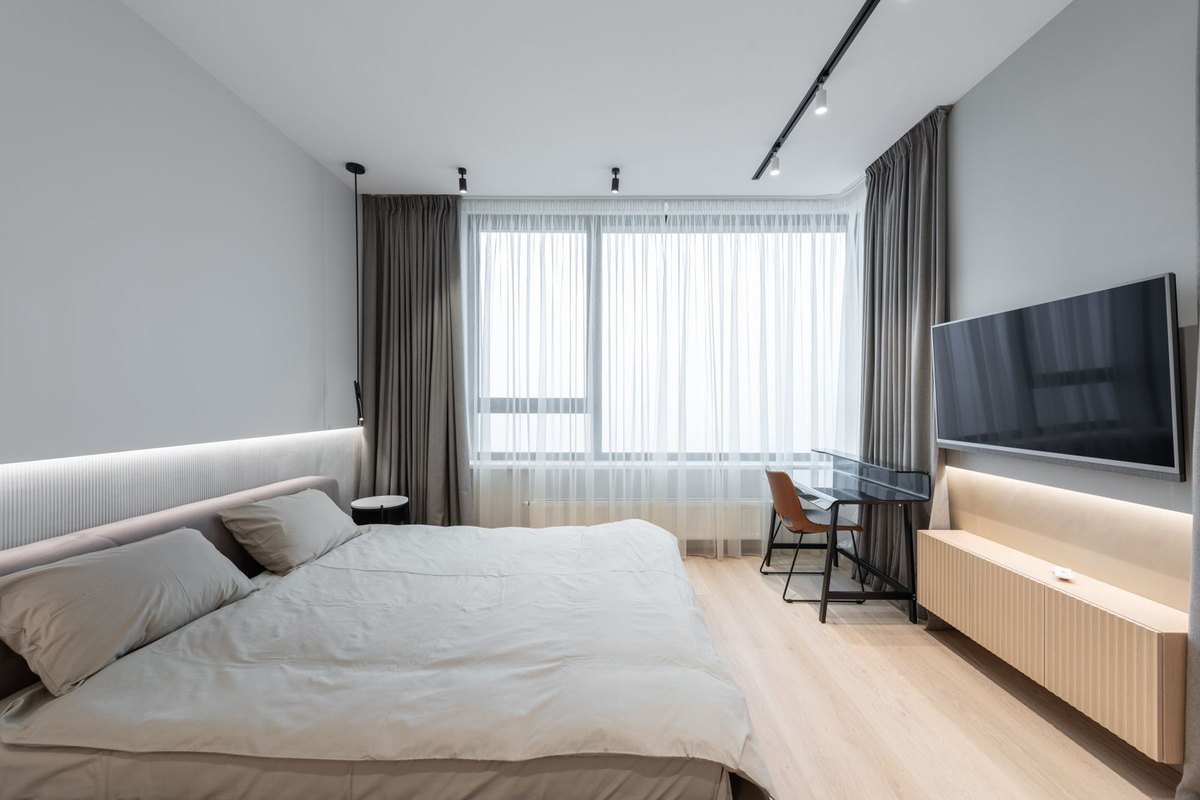
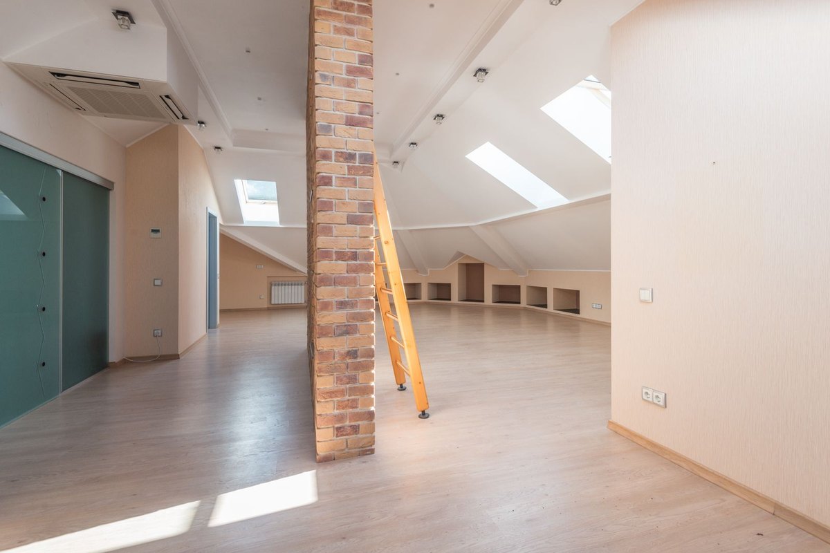
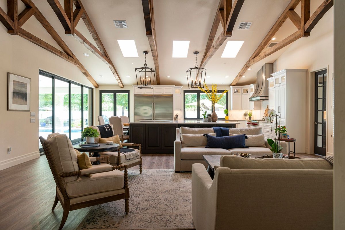
Vacated lofts, attics and vaulted living rooms are the cases where this article earns its keep. A vaulted ceiling is a moving mounting height: heads near the ridge are far higher than heads near the eaves, so a single pitch cannot be right for the whole rail.
Practically there are two workable answers. Either split the rail into zones and give each zone its own pitch, or keep one pitch and accept that the ridge-end heads will spread wider and read dimmer — which is often fine if the ridge is where you want the light to fall away. What does not work is running one pitch across a varying height and expecting even coverage.
If the fixtures are already on the ceiling, you can recover the numbers and see what the layout is actually doing. Measure the pitch between heads first — that is the input you can get most accurately — then work out the pool at the real height and let the overlap fall out of it.
Say the heads sit 3.00 ft apart at 9 ft with 24° optics: the pool is 3.83 ft, so the overlap is 1 − 3.00/3.83 = 22 %. That is accent territory, not general lighting, which explains the separate pools and the darker strips between them. To convert it to general light you would tighten the pitch to 2.68 ft, adding heads rather than changing fixtures.
With 24° heads at 9 ft, put them about 2.68 ft apart centre to centre for general lighting, which is the 3.83 ft pool overlapped by 30 %. Narrower 15° heads should sit about 1.66 ft apart, wider 36° heads about 4.09 ft apart.
Yes, and it must. The pool widens in direct proportion to height, so the pitch has to widen by the same factor or your overlap changes. Going from a 9 ft to a 12 ft ceiling makes the 24° pool 5.10 ft instead of 3.83 ft, so a 30 % overlap needs a 3.57 ft pitch rather than 2.68 ft.
Usually fewer fixtures but more lumens each. A higher ceiling means a wider pitch, so a given rail takes fewer heads, but illuminance falls with height squared: 12 ft keeps about 56 % of the 9 ft floor level and 16 ft keeps 32 %. Budget roughly 1.78× the lumens at 12 ft and 3.16× at 16 ft to hold the same floor illuminance.
About 20 % for accent lighting where you want the pools to read separately, 30 % for general lighting, and 40 % for task light over worktops and desks where a gap between pools would show as a shadow.
Measure the ceiling-to-floor height, halve the beam angle, take the tangent and double it: D = 2 × H × tan(θ/2). Then multiply the pool by (1 − overlap) to get the pitch. For a 36° head at 10 ft that is a 6.5 ft pool and, at 30 % overlap, a 4.55 ft pitch.
Yes, because the relevant distance is the throw to the wall, not the ceiling height. A head 4 ft out from the wall and 4 ft above the artwork centre has a throw of about 5.66 ft, so a 24° beam paints roughly 3.40 ft of wall and arranges as separate pools at around 20 % overlap.
Spacing is two variables, not one. Take the beam angle, take the mounting height, and let D = 2 × H × tan(θ/2) give you the pool. Choose your overlap from what the room has to do — 20 % accent, 30 % general, 40 % task — and the pitch follows. Then scale the pitch whenever the height changes, and resize the lumens at the same time, because the floor loses light with the square of the distance.
If you are choosing heads for a room with a non-standard ceiling, the AIMER track light is offered in 15°, 24°, 38° and 60° optics, and the OVEGA zoomable head tunes across 15°–45° on site, which is what the aiming calculation above needs. For the underlying optics, the beam angle guide covers how the printed angle maps to real light, and the spacing guide takes the overlap decision further. If you tell us the room height and what it needs to do, we will work the layout with you.