Address
304 North Cardinal
St. Dorchester Center, MA 02124
Work Hours
Monday to Friday: 7AM - 7PM
Weekend: 10AM - 5PM
Address
304 North Cardinal
St. Dorchester Center, MA 02124
Work Hours
Monday to Friday: 7AM - 7PM
Weekend: 10AM - 5PM
How far apart should track lighting be? Use beam angle and mounting height to calculate track light spacing, overlap and head counts room by room. Read on.
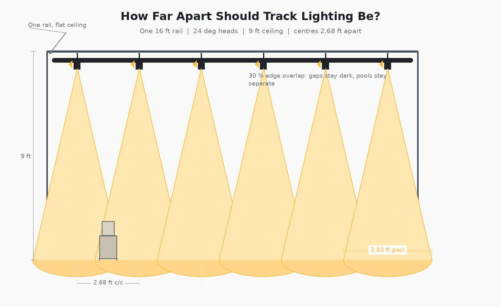
Most people guess. They stand under the ceiling, hold a head in one hand, and eyeball a distance that feels about right. Three months later the room has bright stripes under the rail and dark pools in the corners, and nobody can say exactly why. The honest answer to how far apart should track lighting be is a single number — but that number is not the same in a kitchen as it is over a painting, and it changes every time you raise the ceiling.
This guide gives you the arithmetic behind track light spacing, then the judgement calls: which overlap to use over a dining table, why a gallery wall wants the opposite of a hallway, and what actually happens to your spacing when the ceiling goes from 9 ft to 14 ft. Every figure here assumes a 24° head at 9 ft unless it says otherwise, and every number is worked out in full so you can substitute your own room.
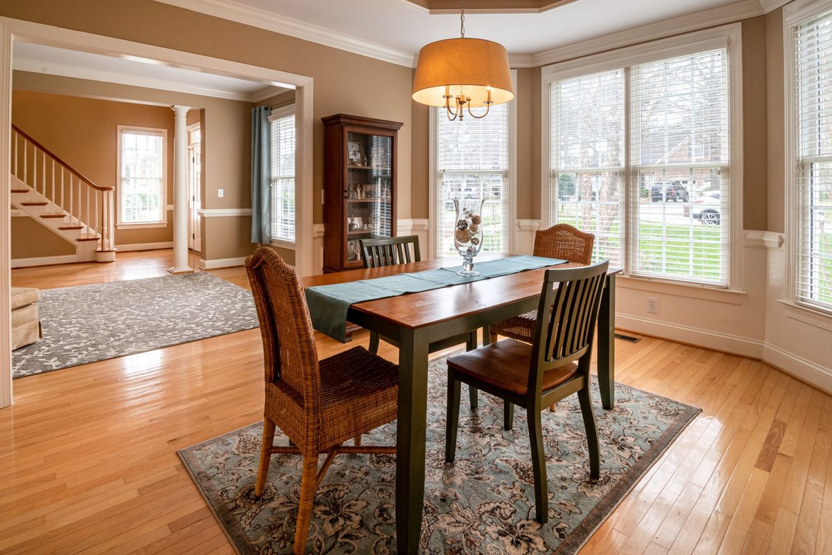
For a typical living room with a 9 ft (2.74 m) ceiling and 24° track heads, place the heads about 2.7 ft (0.8 m) apart centre to centre. That figure comes from a 30 % edge overlap between neighbouring light pools — enough to stop the gaps feeling dark, not so much that the pools disappear into one another.
Three other common starting points, all at 9 ft and all measured centre to centre:
Those numbers are not opinions. They fall out of one calculation, and once you have it you can size any room in about a minute — including rooms with ceilings nothing like 9 ft.
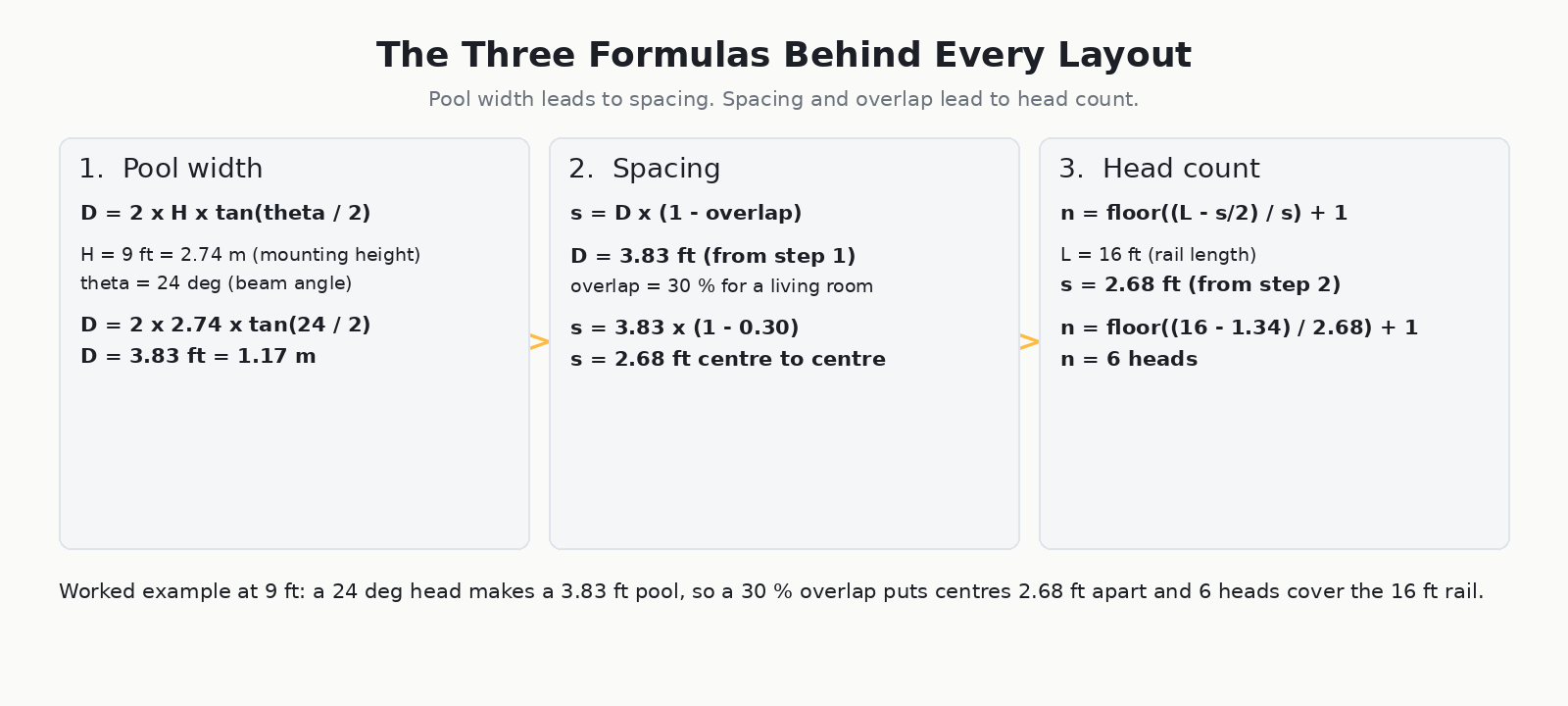
Before you can space anything you need to know the size of what you are spacing. The pool of light a track head throws onto the floor is a circle, and its diameter depends on two things: how far the head is from the surface, and how wide its beam angle is.
The relationship is a right triangle. The beam angle opens symmetrically around the centre line, so you only need half of it, and the pool width is:
D = 2 × H × tan(θ / 2)
D = pool diameter | H = mounting height above the surface | θ = beam angle
At 9 ft (2.74 m) with a 24° head, that is 2 × 2.74 × tan(12°) = 1.17 m, or 3.83 ft. The Illuminating Engineering Society (IES) publishes the reference illuminance levels this spacing is usually judged against. So one head covers a circle a little under 4 ft across. That single fact does most of the work in this article.
The four standard beam angles behave very differently from the same rail, which is exactly why the beam angle you choose is the first decision and spacing is the second:
| Beam angle | Pool at 8 ft | Pool at 9 ft | Pool at 10 ft | Pool at 12 ft |
|---|---|---|---|---|
| 15° narrow spot | 2.11 ft | 2.37 ft | 2.63 ft | 3.16 ft |
| 24° spot | 3.40 ft | 3.83 ft | 4.25 ft | 5.10 ft |
| 36° flood | 5.20 ft | 5.85 ft | 6.50 ft | 7.80 ft |
| 60° wide flood | 9.24 ft | 10.39 ft | 11.55 ft | 13.86 ft |
Read the 24° row carefully. Going from an 8 ft ceiling to a 12 ft ceiling grows the pool by half again — 3.40 ft becomes 5.10 ft. If you keep the same spacing on both floors you will get a room that looks correct downstairs and pockmarked upstairs. Height is not a detail; it is half the equation.
Two neighbouring pools can sit any distance apart. The variable that connects pool width to spacing is edge overlap: how much of each pool the next one covers. Express it as a percentage of the pool diameter and the arithmetic is trivial.
spacing = pool width × (1 − overlap)
At 9 ft with a 24° head (3.83 ft pools), a 30 % overlap gives 3.83 × 0.70 = 2.68 ft centre to centre. That is the 2.7 ft figure from the top of this article.
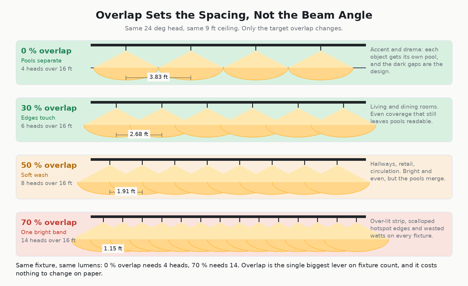
What changes from room to room is not the formula but the overlap you pick. There are three useful regimes:
That is the entire trick. Spacing is not a fixture property; it is the distance that produces the pool relationship you asked for.
Once you have spacing, the head count is a division. Leave half a spacing at each end so the first and last pools are not clipped by the wall:
n = floor((L − spacing / 2) / spacing) + 1
For a 16 ft rail at 2.68 ft spacing: floor((16 − 1.34) / 2.68) + 1 = 6 heads. Six heads, evenly spaced, cover the run with a 30 % overlap and no dead ends.
This is the step people skip, and it is where budgets go wrong. Drop the overlap from 30 % to 0 % over the same 16 ft and you need only four heads. Push it up to 50 % and you need eight. The lux level you are targeting does not change at all — only how evenly it is spread. Overlap is the single largest lever on fixture count, and it costs nothing to change on paper.
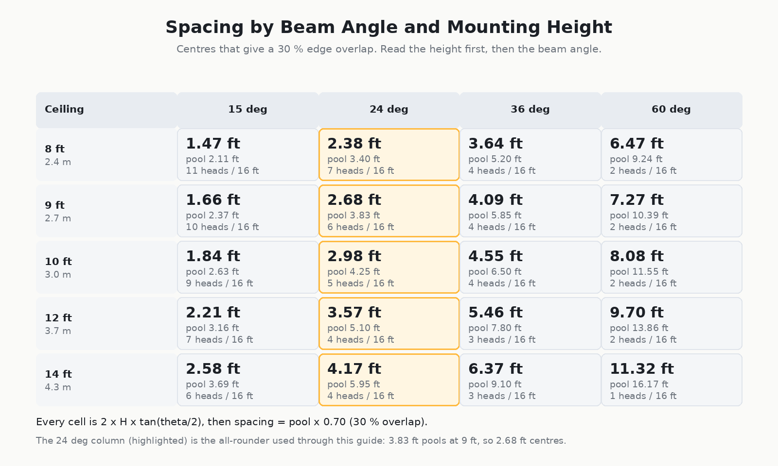
The formula is constant. The overlap is not. Here is how the same maths plays out room by room at a 9 ft ceiling.
Two or three parallel rails running the long axis, heads at 2.5–3.0 ft with a 24° beam, 30 % overlap. Aim at the areas between furniture rather than at the furniture; you want the floor to read as evenly lit with soft pools that catch chair arms and coffee tables. If the ceiling is above 10 ft, either step up to a 36° head or accept wider spacing.
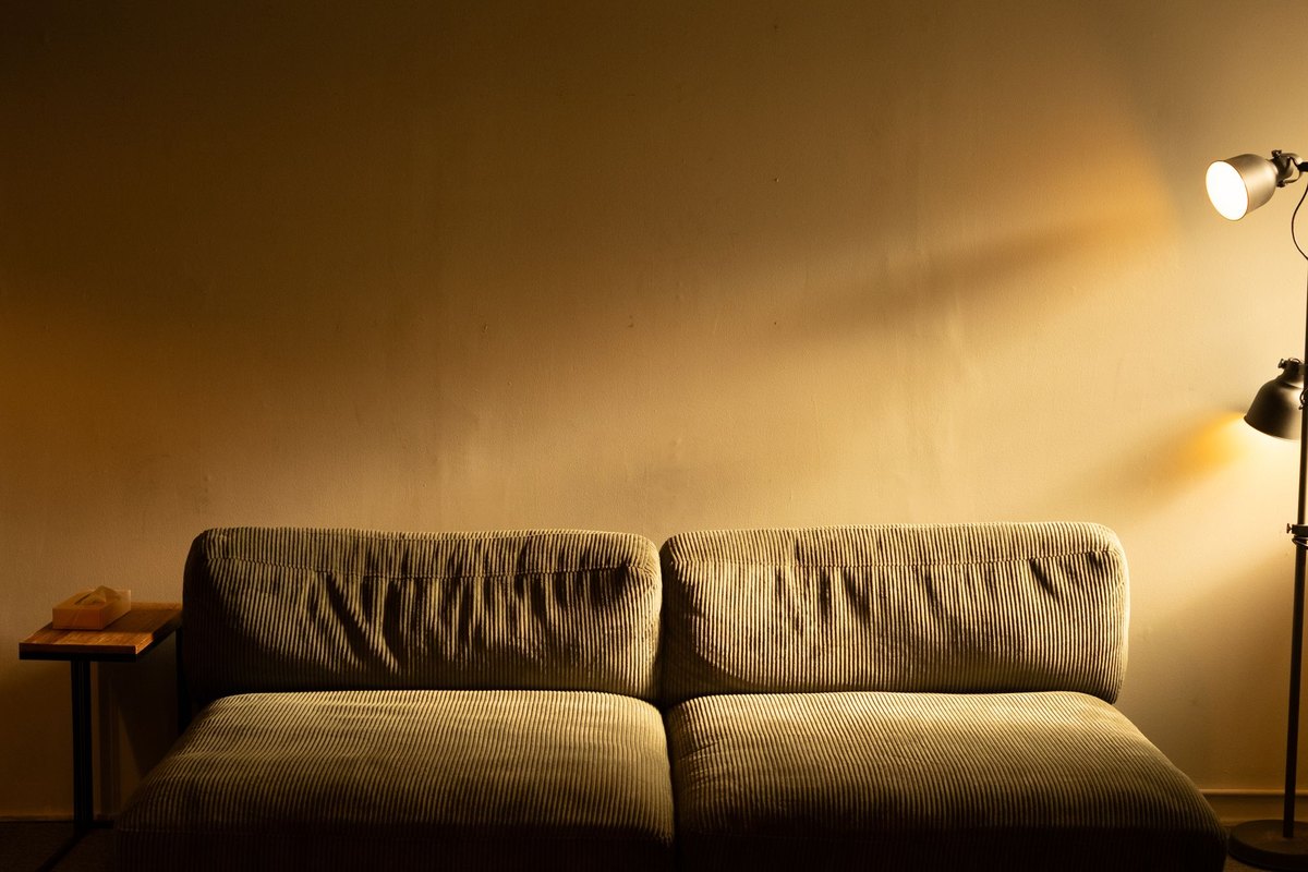
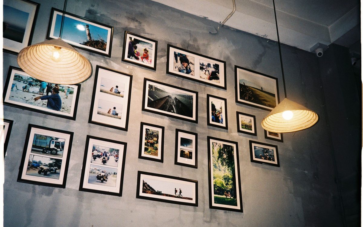
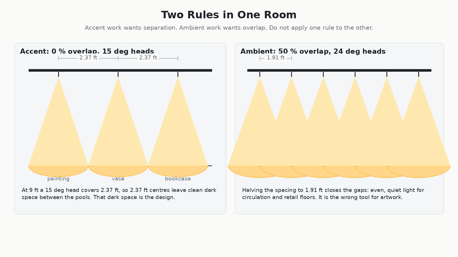
This is the one place you reverse the rule. Narrow 15° heads at 2.0–3.0 ft, and 0 % overlap — one head per frame, aimed so the top of the frame is brighter than the bottom. The dark space between pools is not a flaw to be fixed; it is what makes each piece read as a separate object. If your spacing is tight enough that the pools touch, you are lighting a wall, not a collection.
Light the tabletop, not the room, and put the heads over the long edges of the table rather than the centre — that is where plates and faces actually are, and it keeps light out of seated eyes. Two heads per side, spaced about half the table’s length apart, 24° at 0 % overlap. Over a 6 ft table that is roughly 3 ft between heads. The same reasoning that governs a pendant over a dining table applies to a track head: aim at the surface, and keep the beam off the eye line.
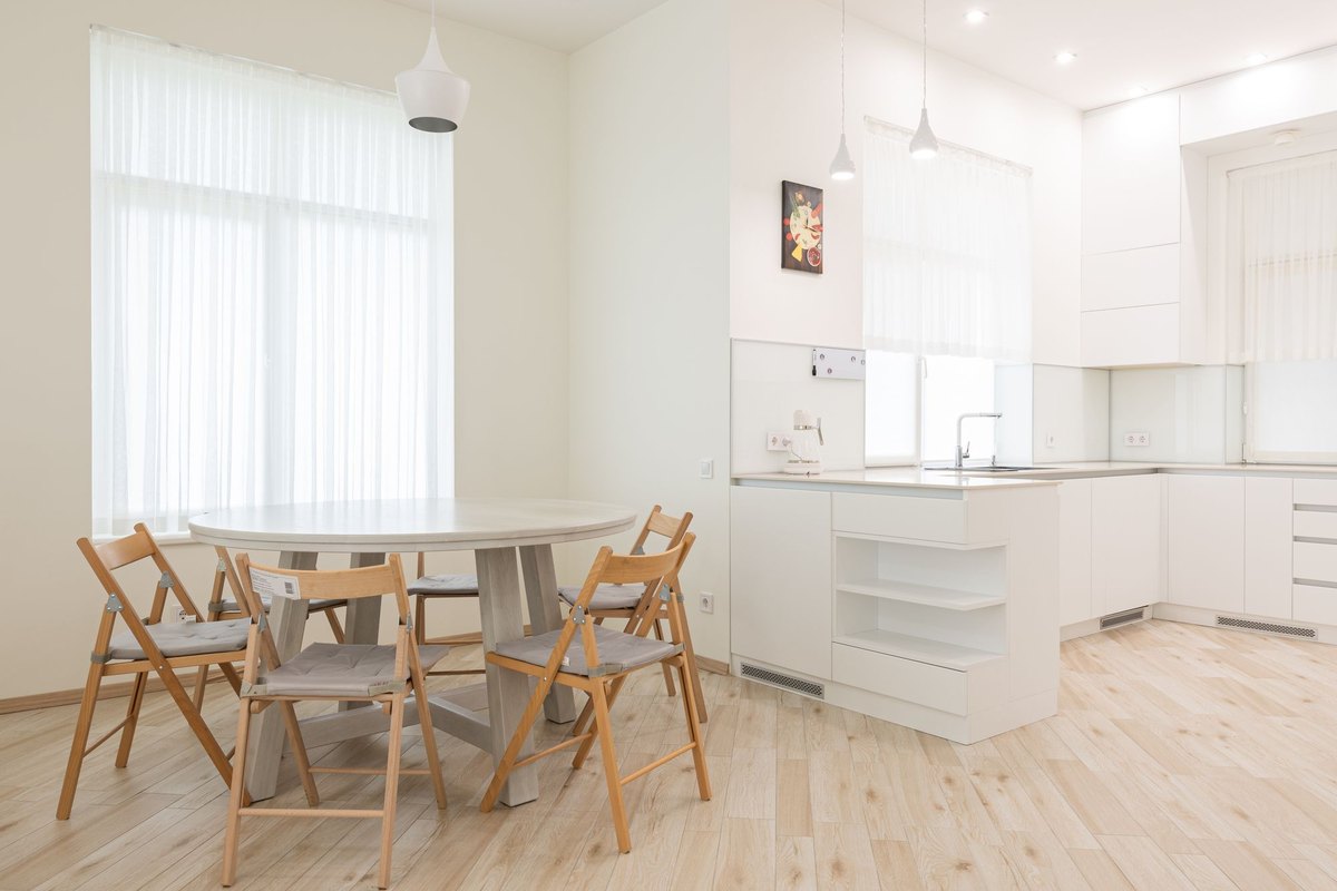
The island is the one place where overlap genuinely earns its extra fixtures. Use 36° heads at 2.5–3.5 ft with a 20 % overlap so the whole worktop reaches a usable 300–500 lux. On a long island — 8 ft and up — use two rows, one either side of the centreline, rather than one row trying to cover the full depth.
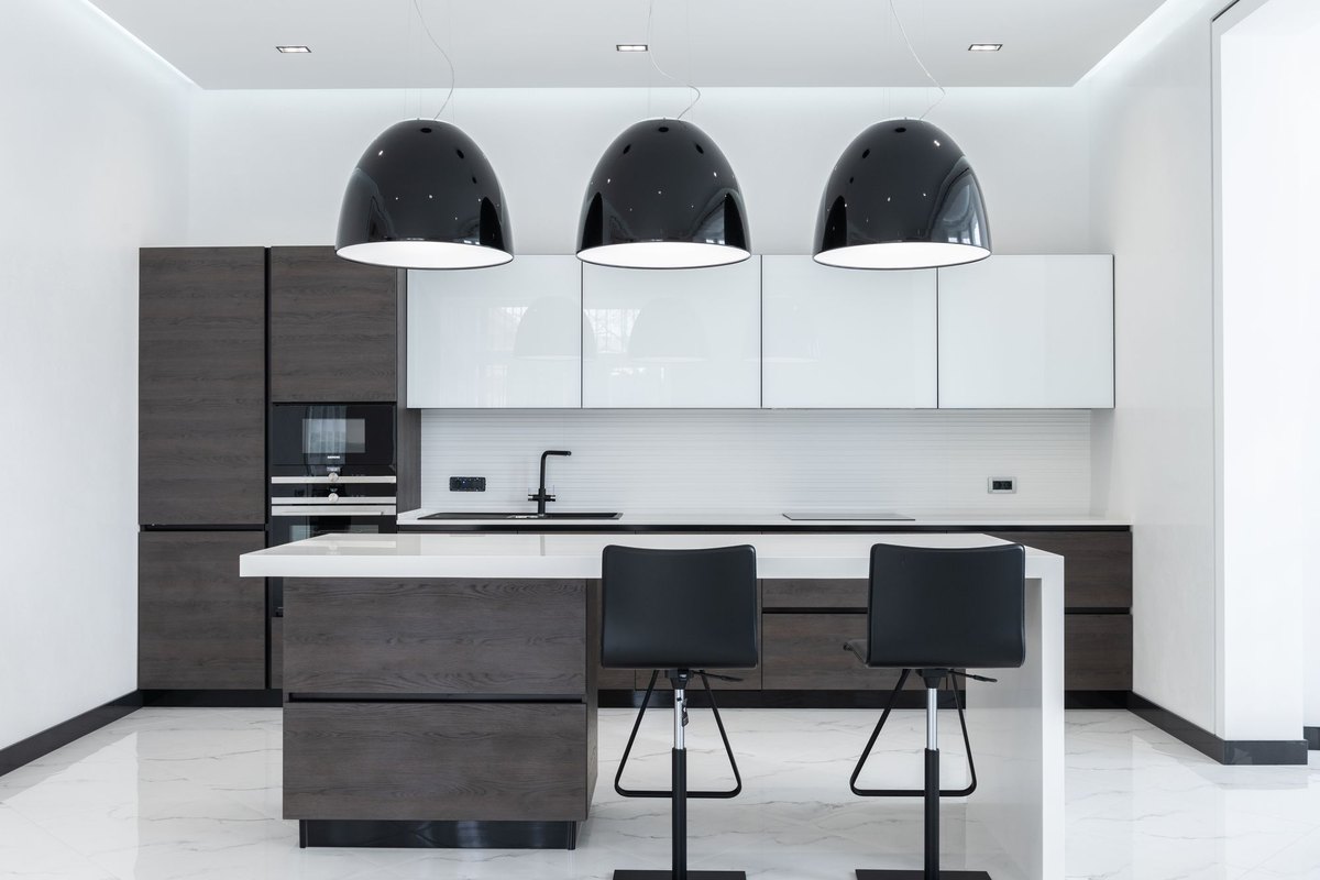
Single file along the axis, 60° heads at 4.5–5.5 ft, 40 % overlap. A hallway is pure circulation: nobody looks up, and even light at low contrast is the correct answer. This is also the most forgiving place to learn the formula, because a mistake reads as a slightly brighter or darker patch rather than as a design failure.
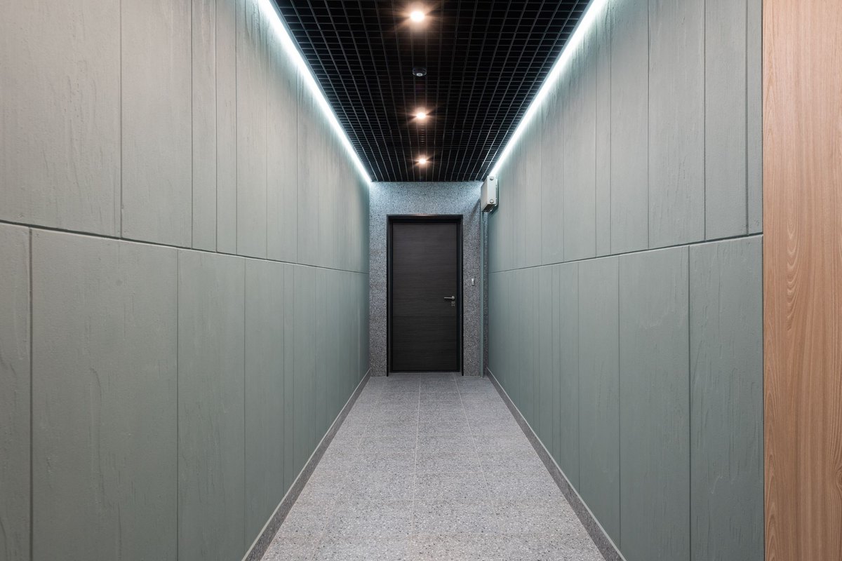
Two jobs, two spacings. Wall-washing 36° heads at 3.0–4.0 ft along the headboard wall for ambient glow, plus a single 24° head per side as a reading light, aimed at the page rather than the pillow. If you sleep badly, keep the ambient layer on a dimmer and separate from the reading pair.
This is where most home layouts quietly fail. A pool grows in direct proportion to the mounting height, so if the ceiling rises by a third the pools grow by a third — and the spacing you worked out downstairs is now too tight or too loose, depending on which way you moved.
The correction is straightforward: scale your spacing by the height ratio. Going from a 9 ft to a 12 ft ceiling with the same beam angle means spacing goes from 2.68 ft to 3.57 ft (a factor of 12/9 = 1.33). If you would rather keep the spacing and change the optics instead, drop from a 36° head to a 24° head, which keeps the pool roughly the same size from a taller ceiling.
There is a second effect, and it is the one people feel rather than measure. Illuminance falls with the square of the distance, so the same fixture at 12 ft delivers about 56 % of the light it delivered at 9 ft, and at 14 ft about 41 %. You cannot fix that by moving heads closer together — you need more output or a narrower beam. The U.S. Department of Energy notes the same fall-off as the main reason LED retrofits need a fresh layout rather than a one-for-one swap. A track head with an interchangeable reflector lets you change the optics on site once the room is built, which is worth far more than a spreadsheet that was correct on paper.
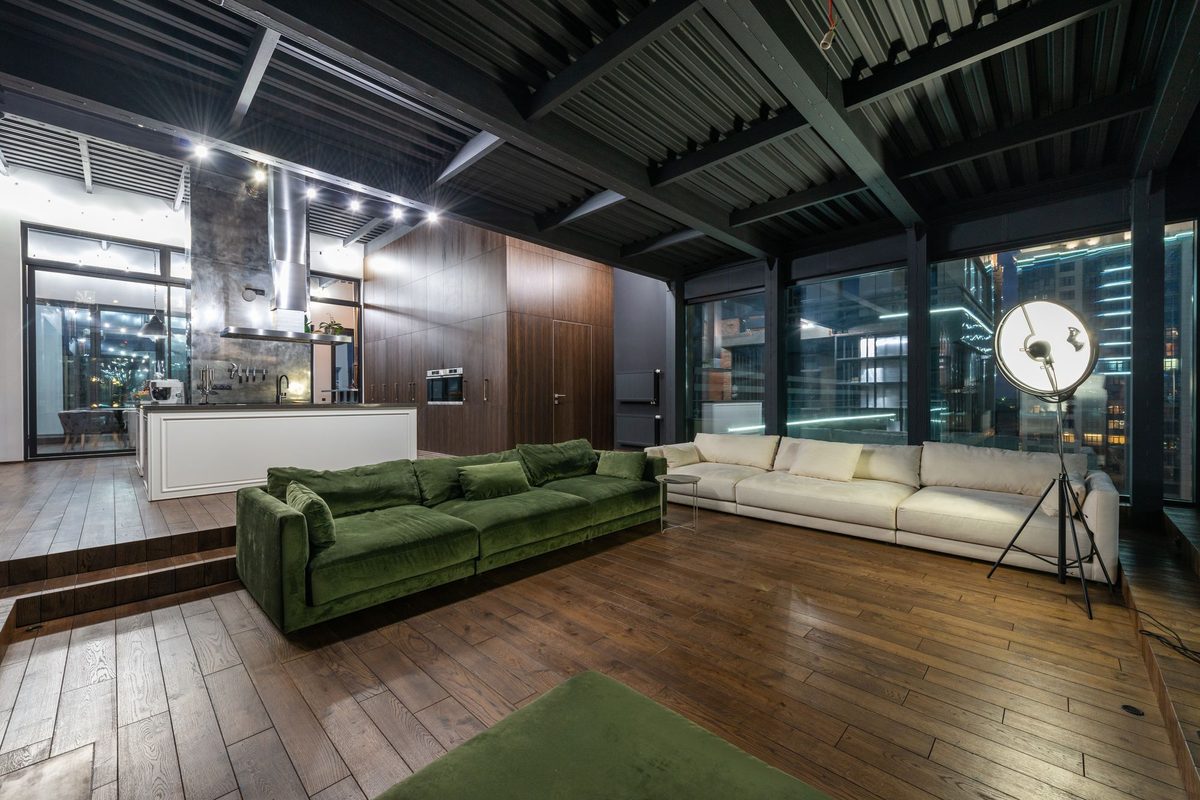
Almost every residential track layout is a variation on one of these. The spacing number stays the same; what changes is the line the heads sit on.
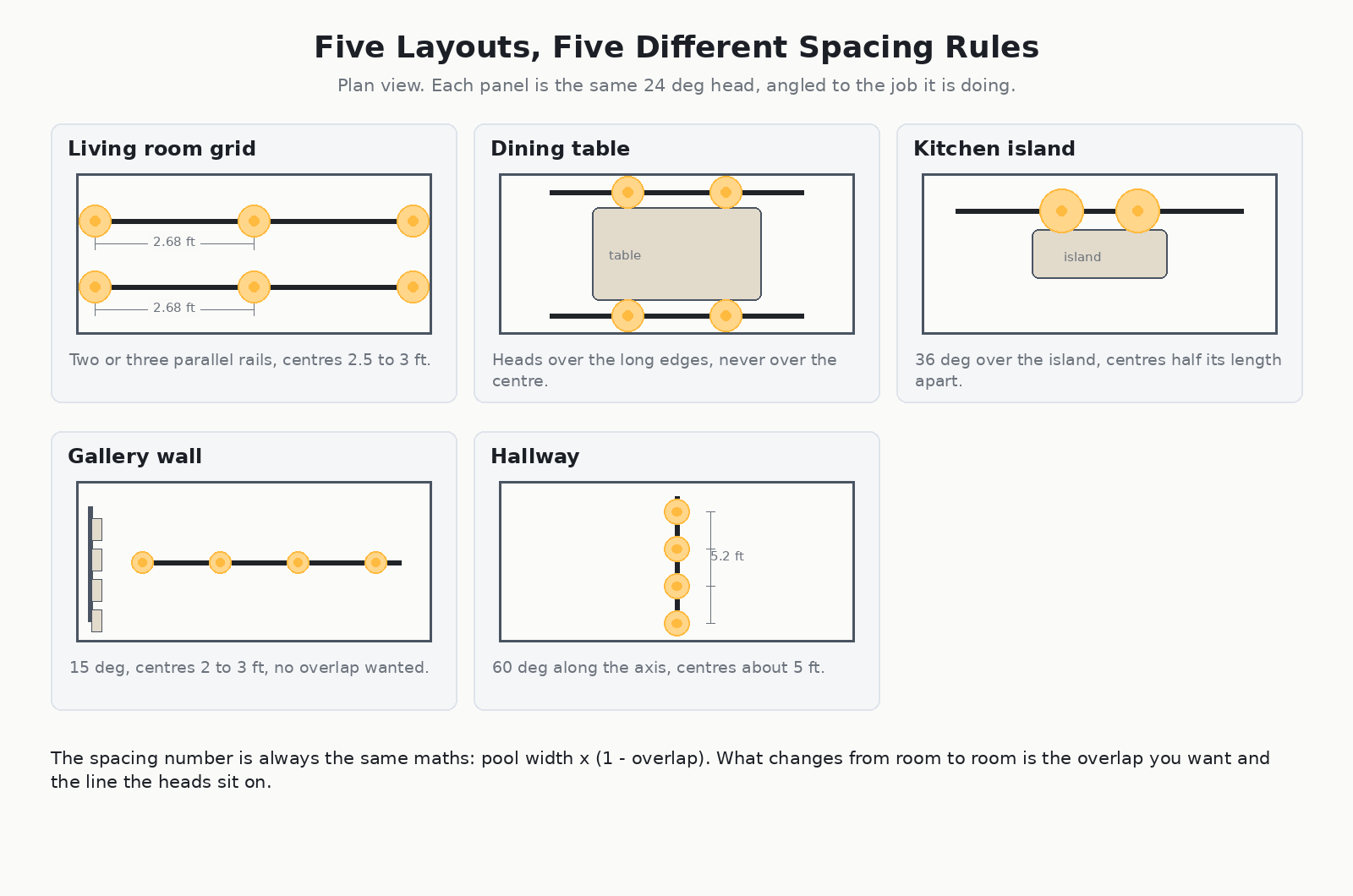
The default for square rooms. Rails run the long axis, 4–6 ft apart, heads at 2.5–3.0 ft. Two rails are usually enough for a room up to about 16 ft wide; beyond that, add a third or increase the rail separation and the beam angle together.
Rails follow the walls and heads wash inward. Excellent for rooms with a central feature you do not want to flatten, and for ceilings with structural beams that dictate where a rail can be fixed. Use it when you want the walls brighter than the floor.
Heads are grouped where work happens — over an island, a desk, a counter — and left sparse elsewhere. Spacing within a cluster follows the 20–30 % overlap rule; the space between clusters is deliberately dark. This is the most energy-efficient pattern and the most common in commercial interiors.
A single rail 2–3 ft off the wall, heads tilted toward it, 36° or wider, spaced at 30 % overlap. It flattens texture on purpose and makes a room feel taller. Useful in retail where merchandise needs even coverage, and in living rooms with a large blank wall.
One rail, few heads, 15° optics, 0 % overlap, each head aimed at a specific object. This is where spacing stops being a formula and becomes a decision about which three things in the room deserve to be seen.
The mistake people make is picking one overlap and applying it everywhere. In practice a single room usually needs both: a separated accent layer for the things you want to see, and an overlapped ambient layer so you can walk around without dark holes.
If the rails are already up and you just want to know what you own, run the formula in reverse. Measure the centre-to-centre distance between two heads and the height of the ceiling, then:
θ = 2 × arctan(D / (2H))
Two heads 4.25 ft apart on a 9 ft ceiling implies a pool of 4.25 ft if you want them just touching, which corresponds to a beam angle of about 26°. In practice that means your 24° heads are very slightly wide for the spacing, which is fine — that is a 10 % overlap nobody will notice. Doing this check before you buy replacement optics saves a second order.
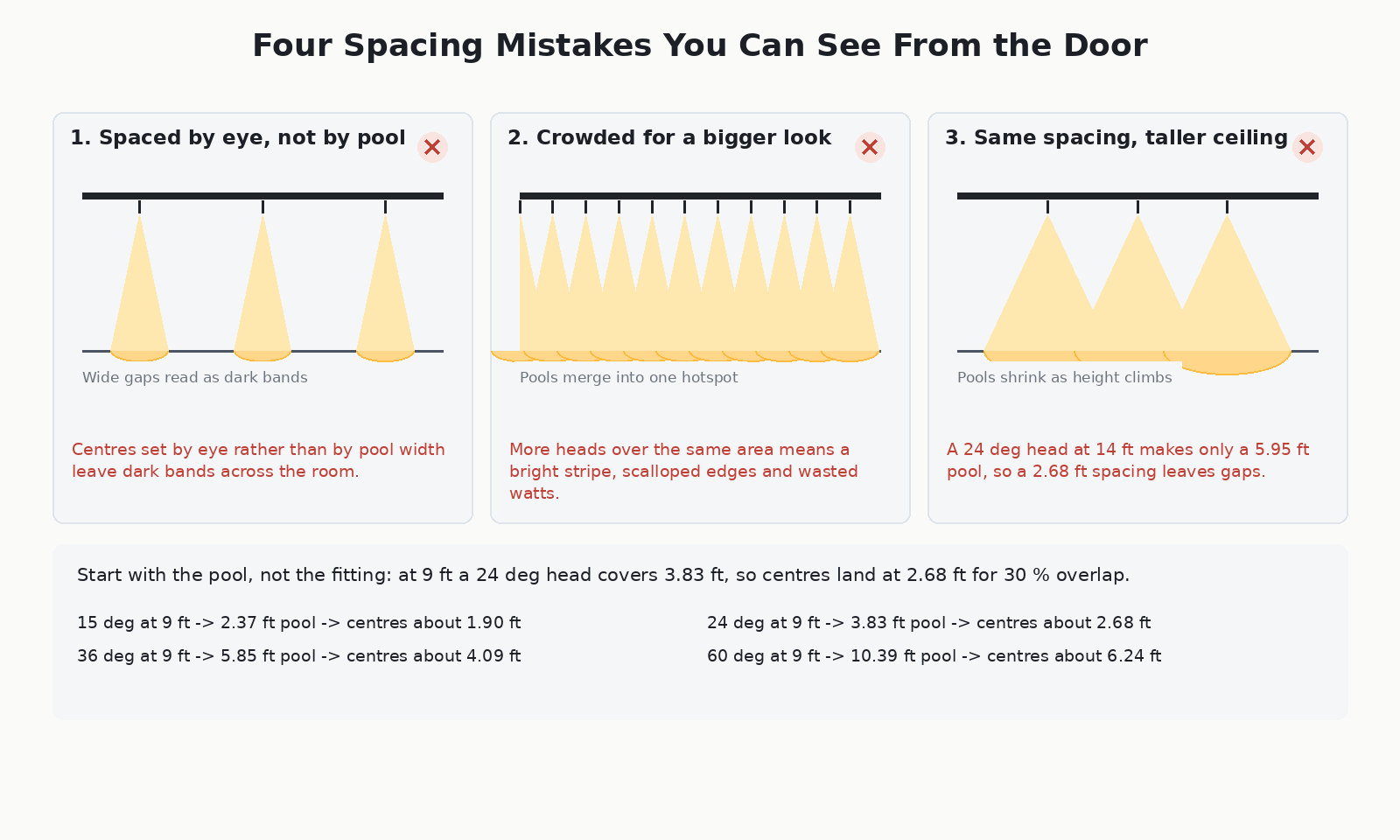
At a 9 ft ceiling with 24° track heads, space them about 2.7 ft apart centre to centre. That gives a 30 % edge overlap between the 3.83 ft light pools, which is the standard starting point for living rooms and dining areas. Narrow 15° accent heads want about 2.4 ft, wide 36° heads about 4.1 ft, and 60° circulation heads about 6.2 ft.
Usually, yes — but the amount depends on the job. A 30 % overlap keeps light even while leaving the pools readable, which is right for living space. Accent lighting is the exception: over artwork you want 0 % overlap, so each piece sits in its own pool with deliberate darkness around it. Retail floors and hallways often run 40–50 % because even coverage matters more than modelling.
Three steps. First find the pool width: D = 2 × H × tan(θ/2), where H is the mounting height and θ the beam angle. At 9 ft with a 24° head that is 3.83 ft. Second, apply your overlap: spacing = D × (1 − overlap). At 30 % overlap, 3.83 × 0.70 = 2.68 ft. Third, divide the rail length by the spacing, leaving half a spacing at each end, to get your head count.
Yes, and it changes proportionally. Pools grow with mounting height, so a 12 ft ceiling needs roughly 33 % wider spacing than a 9 ft ceiling for the same beam angle and overlap — 3.57 ft instead of 2.68 ft with 24° heads. Output drops too: the same fixture delivers about 56 % of its 9 ft illuminance at 12 ft, so height usually means both wider spacing and more output.
No — the difference is large. At 9 ft a 15° head throws a 2.37 ft pool and a 60° head throws a 10.39 ft pool, a factor of more than four. The same 2.7 ft spacing that gives a comfortable 30 % overlap with 24° heads would make 60° heads overlap by nearly 75 %, which wastes light and flattens the room.
Six, with 24° heads at 9 ft and a 30 % overlap. The calculation is floor((16 − 2.68/2) / 2.68) + 1 = 6. Drop the overlap to 0 % and four heads are enough; raise it to 50 % and you need eight. The lux level stays the same either way — only the evenness changes.
The question “how far apart should track lighting be” has one honest answer: far enough apart that the light pools sit in the relationship you want, and no further. At 9 ft with 24° heads that is about 2.7 ft for general living space, 2.4 ft for accent work with deliberate gaps, and 4–6 ft for wider floods in corridors and on retail floors.
Get the pool width first, choose your overlap second, and let the head count fall out of the division. Do that and the layout stops being a guess — and it will still hold when you move to a room with a taller ceiling.
If you would rather not run the numbers alone, our team sizes track layouts for museums, retail and residential projects every week. Have a look at the track light range — every head in it takes interchangeable 15°, 24°, 38° and 60° reflectors, so spacing stays adjustable after installation — or send us your room dimensions and ceiling height and we will return a spacing plan with a fixture schedule.