Address
304 North Cardinal
St. Dorchester Center, MA 02124
Work Hours
Monday to Friday: 7AM - 7PM
Weekend: 10AM - 5PM
Address
304 North Cardinal
St. Dorchester Center, MA 02124
Work Hours
Monday to Friday: 7AM - 7PM
Weekend: 10AM - 5PM
Museum lighting design in practice: how to budget lux against exposure hours, calculate UV load in mW/m2, and specify conservation-safe filters and layouts.
Museum lighting design is judged on two numbers, and only one of them is a light level. The first is illuminance, in lux. The second is the total dose that illuminance delivers over a year, in lux-hours. A painting can survive 50 lx for a thousand hours, or 100 lx for five hundred — the object sees the same 50,000 lx·h either way. That product, not the lux figure, is what a conservation department actually protects.
This guide sets out how to run that budget, how to quantify the ultraviolet load that comes with it, and how to translate both into a specification you can hand to a contractor. All the geometry and arithmetic below is the same arithmetic used to draw the figures, and it is printed so you can check it. The exposure-budget and UV-limit conventions referenced here follow current museum practice as set out by the Illuminating Engineering Society and the International Commission on Illumination (CIE); for material-specific sensitivity guidance, the Canadian Conservation Institute publishes the most widely used agent-of-deterioration references.
Photochemical damage is cumulative and irreversible. Bleaching, yellowing and embrittlement are the result of photons breaking chemical bonds, and the number of bonds broken is proportional to the number of photons absorbed — not to how bright the room looked on any given afternoon.
That is why the standard is written as an annual exposure budget. For highly sensitive material — works on paper, textiles, watercolours, illuminated manuscripts — a common curatorial budget is 50,000 lux-hours per year. A 90% safety factor is normal practice, which leaves 45,000 lx·h of usable budget.
The consequence is counter-intuitive for anyone used to specifying domestic lighting. Raising illuminance from 50 lx to 100 lx does not make the room slightly brighter — it halves the display time.
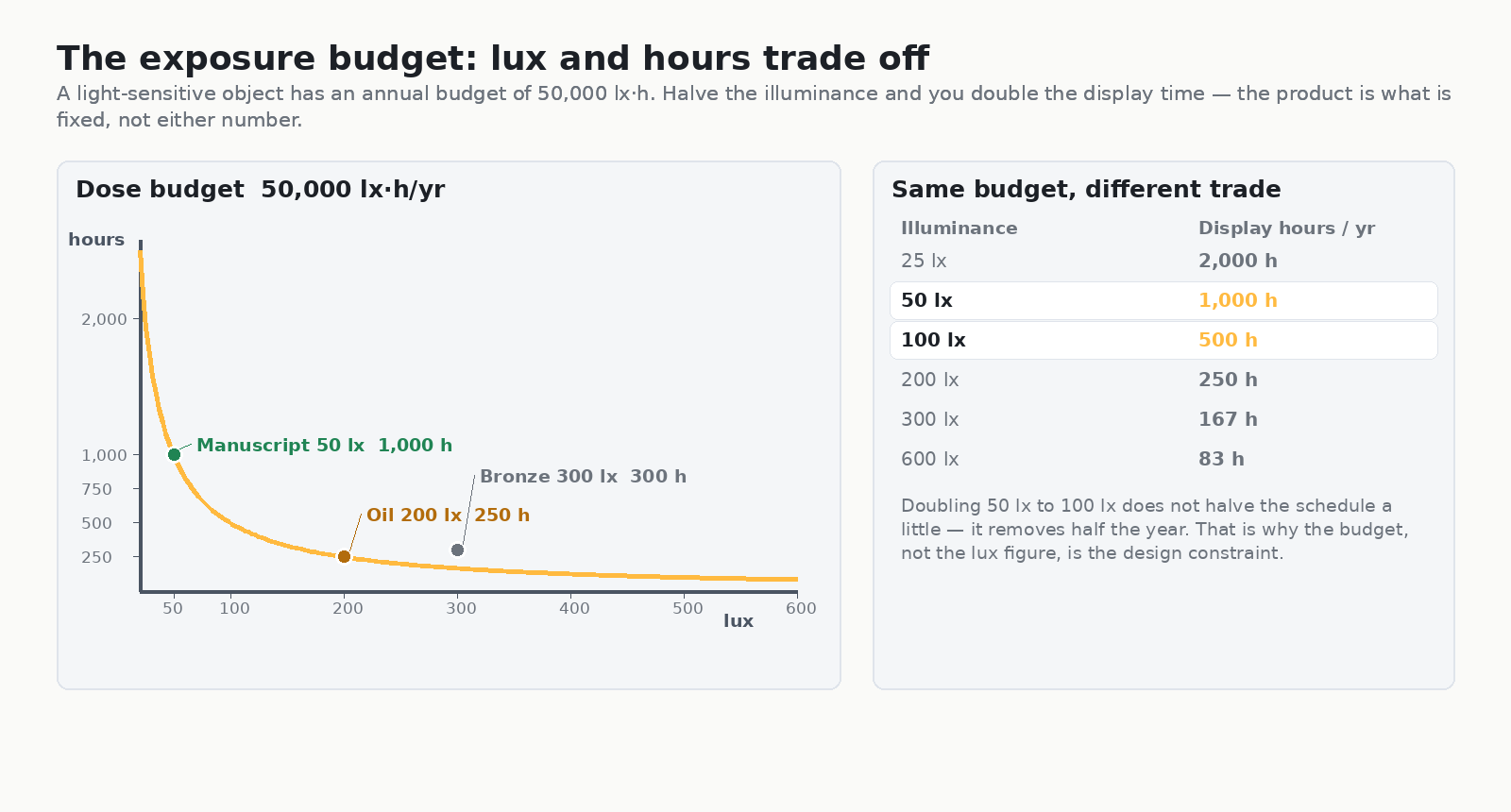
A budget of 45,000 usable lx·h at 50 lx works out to 900 hours a year. Spread across 365 days that is 2.47 hours per day, or a duty cycle of 10.3% of the year. That is the number a gallery actually operates against: not “the dimmer is at 50 lx”, but “this case is lit 2.5 hours a day”.
In practice most institutions run a shorter, brighter daily window. Three forty-minute guided tours at 50 lx is two hours — comfortably inside budget, with headroom for conservation photography and condition checking.
The budget is what limits exposure; the illuminance target is set by the material’s sensitivity. The figures below are the working range used across conservation literature, paired with the hours each one buys inside a 50,000 lx·h budget.
| Material class | Typical illuminance | UV limit | Hours at 50,000 lx·h |
|---|---|---|---|
| Highly sensitive — works on paper, textiles, manuscripts, dyed leather | 50 lx | 75 µW/lm | 1,000 h |
| Sensitive — oil and tempera paintings, wood, ivory, horn | 150–200 lx | 75 µW/lm | 333–250 h |
| Moderately sensitive — stone, ceramics, glass, metal with applied colour | 300–500 lx | 75 µW/lm | 167–100 h |
| Insensitive — uncoloured stone, most metals, glass without coatings | No practical limit | UV still controlled | Not the constraint |
Two things about that table catch people out. First, low illuminance does not mean the UV problem went away — UV sensitivity and visible-light sensitivity are different mechanisms, and a bronze can be lit hard and still be damaged by an unfiltered source. Second, the hours column is where the operative constraint lives. A 200 lx painting in a room open seven hours a day exhausts its budget in under six weeks of continuous display.
Ultraviolet is not specified in lux or in watts. It is specified as microwatts of ultraviolet per lumen (µW/lm), which is a ratio: it tells you how much UV comes along for the ride with every lumen of visible light the lamp produces. The museum limit is 75 µW/lm.
To see whether a source passes, convert the ratio into an irradiance at the object. At 50 lx the object receives 50 lm/m², so:
UV load (mW/m²) = illuminance (lm/m²) × UV content (µW/lm) ÷ 1000
Run the numbers for the two sources that matter in a gallery and the picture is stark.
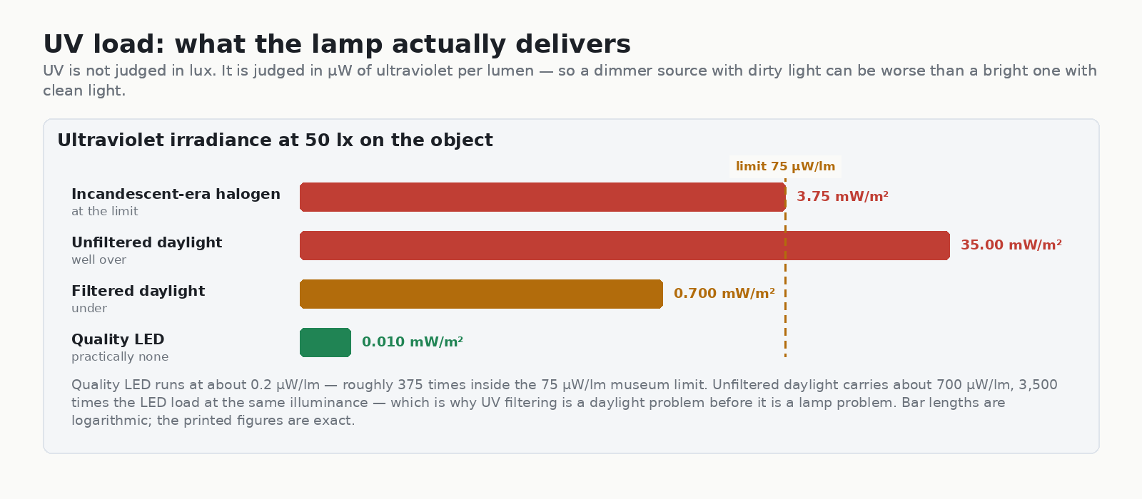
This is the single most useful reframing in museum lighting design practice: UV control is a daylight problem before it is a lamp problem. A conservation-grade LED on a track contributes nothing worth measuring, while an unfiltered rooflight fifteen metres away can be the dominant risk in the room.
Specify UV-absorbing filters on any aperture with a direct line of sight to an object, and require a UV content declaration — in µW/lm — from the luminaire manufacturer. Where an existing scheme uses incandescent-era halogen, note that it sits essentially at the limit: 75 µW/lm produces 3.75 mW/m² at 50 lx, which is to say at the ceiling of what is acceptable, and that is before the infrared contribution is considered.
Radiation below 700 nm does not break chemical bonds the way UV does, but it deposits heat. On a framed panel the failure mode is mechanical rather than photochemical: a canvas expands and contracts against its stretcher, gesso and paint develop differential movement, and the result is craquelure and lifting.
Two design consequences follow. Keep infrared-emitting sources off the object’s axis and out of the frame’s plane, and aim so that the beam passes across a surface rather than parking on it. Track lighting suits this because each head can be angled independently — which brings the geometry into play.
Once you have an illuminance target, the luminaire specification is a calculation, not a guess. Illuminance falls with the square of the distance, so:
E = I / h², therefore I = E × h²
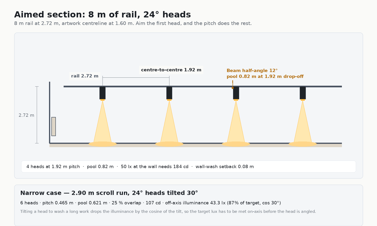
Take a gallery wall with the rail at 2.72 m and the artwork centreline at 1.60 m. The vertical drop from head to the point being lit is 1.92 m. For a 50 lx target at the wall, that requires 184 cd from each head — a modest output, which is exactly why conservation spaces are lit with low-wattage, tightly-controlled fittings rather than bright ones.
Pool width follows from beam angle and drop-off distance:
D = 2 × h × tan(θ/2)
A 24° head at 1.92 m produces a 0.82 m pool. At a spacing criterion of 1.0 — adjacent pools just touching — the centre-to-centre pitch equals the drop-off distance, so 1.92 m. Over an 8 m rail that yields four heads.
Where the work is longer than it is tall, the geometry changes. A 2.9 m scroll run lit by 24° heads tilted 30° off-axis needs 0.465 m pitch to hold 25% overlap, giving six heads. Tilting costs light: the off-axis illuminance falls by the cosine of the tilt, so 50 lx on-axis becomes 43.3 lx at 30° — 87% of target. Meet the target on-axis first, then angle the head.
The most common layout error in conservation spaces is spacing heads before deciding the aiming point. Because illuminance falls with the square of the distance, a head aimed at a point further away needs disproportionately more output. Fix the aiming point on the object’s centreline, calculate the drop-off, derive the pool and the pitch, then place the heads. Changing the aim afterwards invalidates the whole chain.
Track systems are the usual choice for conservation galleries for three reasons: the aim of each head is independently adjustable, head positions can be changed without touching the fabric of the building, and accessories — UV filters, glare control, snoots — clip on at the head rather than being designed into the ceiling.
A specification that survives contact with a conservation department covers these points:
| Item | What to specify | Why |
|---|---|---|
| UV content | ≤ 75 µW/lm, declared by the manufacturer | Converts a ratio into a checkable figure |
| Infrared | No IR-emitting source on axis with the object | Removes the differential-heating failure mode |
| Colour rendering | Ra ≥ 90, ideally ≥ 95 for pigment matching | Wrong colour temperature changes perceived hue and can force illuminance up |
| Beam angle | Matched to the pool size, not to a room dimension | Pool is the controlled variable; spill is wasted dose |
| Aiming | Independent per head, with a locking mechanism | Stops drift over the life of the exhibition |
| Glare | Deep-set or accessory-controlled heads | Visitor comfort, and it keeps the light off the glass |
| Dimming | Dimmable to at least 10% | Lets the daily budget be managed rather than fixed |
On the luminaire side, the fittings that suit this work are the ones with narrow, well-controlled distributions and genuine aim adjustability. Our AIMER track light is built for exactly this pattern — a tight beam at modest output, with the head aimed per position rather than the whole run set to one angle. For wall-mounted cases and panel edges, the OVEGA zoomable wall-mounted fitting lets the beam be narrowed on site as the pool requirement firms up. Browse the wider lighting guides for the optics behind these numbers, or see the full track light range.
It depends on the material. Highly sensitive objects — works on paper, textiles, manuscripts — are held to about 50 lx. Oil paintings and other moderately sensitive works sit at 150–200 lx, and robust materials such as stone and metal can take 300–500 lx. The illuminance is set by sensitivity, but the display schedule is set by the annual exposure budget.
Multiply illuminance by the hours the object is lit, and keep the product under the budget. Highly sensitive material is commonly budgeted at 50,000 lux-hours per year. At 50 lx that allows 1,000 hours; applying a 90% safety factor gives 900 hours, or 2.47 hours a day.
The limit is 75 microwatts of ultraviolet per lumen (µW/lm). To check a source, multiply the illuminance in lm/m² by its UV content in µW/lm and divide by 1,000 to get milliwatts per square metre. A quality LED at 0.2 µW/lm yields 0.010 mW/m² at 50 lx; unfiltered daylight at 700 µW/lm yields 35 mW/m², which is 9.3 times the limit.
Quality LEDs emit almost none — typically around 0.2 µW/lm, roughly 375 times inside the 75 µW/lm limit. The UV risk in a gallery almost always arrives as daylight through unfiltered glazing or rooflights, not from the artificial lighting.
Set the pitch from the pool, not the rail. Calculate the drop-off from head to object, derive the pool width from the beam angle, then space heads at the drop-off distance for pools that just touch. In the worked example here — 2.72 m rail, 1.60 m artwork centreline, 24° heads — that gives a 0.82 m pool and 1.92 m centre-to-centre, so four heads over an 8 m rail.
Usually yes. UV-absorbing filters clip onto the head or the track accessory slot, but confirm two things first: that the filter does not overheat at the lamp’s output, and that the accessory is compatible with the head’s beam angle. Filters that sit in the beam can also alter the distribution, so re-check the pool width after fitting.
Museum lighting design comes down to running three numbers in the right order. Start with the material’s sensitivity to fix the illuminance, convert that into an annual budget in lux-hours to fix the display schedule, then derive beam angle, pitch and candela from the drop-off distance so the photometric specification is a calculation rather than a preference. Check the UV content against 75 µW/lm, and remember that in most galleries the daylight is the larger risk than any luminaire on the track.
If you are specifying a conservation or gallery project and want the optical side worked through against your own drop-off distances and object sizes, send us the drawings and we will run the numbers.